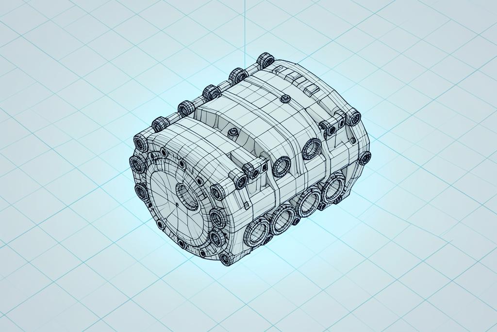
3D CAD design, from a mechanical engineering standpoint
Every model is built to be made. We work in Fusion 360 and SolidWorks, resolving loads, fits, tolerances and manufacturing constraints as part of the design — not as a revision after the first failed part.
What we do
We take a brief, a sketch, a worn-out part or an existing assembly and produce a fully defined 3D model with the drawings and data to manufacture it. Work ranges from a single bracket through to multi-part assemblies with moving interfaces and fastener stacks.
Because we also print the parts, the design decisions are made with the process in mind: wall thicknesses, layer orientation for load paths, support strategy, shrink compensation and post-machined features are all considered up front.
Design for additive manufacture
Parts designed for milling rarely print well, and parts designed for printing rarely need to be milled. We rework geometry for the process — consolidating assemblies into single prints, adding internal ribbing instead of solid mass, and aligning fibre-filled material along the direction of load.
Reverse engineering
Where there is no CAD, we scan the part and rebuild it as clean parametric geometry — not a frozen mesh — so it can be dimensioned, modified and versioned like any other engineered component.
Key specifications
- CAD packages
- Autodesk Fusion 360 · SolidWorks
- Modelling
- Parametric solid & surface
- Assemblies
- Multi-body, mates & motion study
- Drawings
- 2D GA & detail drawings, GD&T
- Native formats
- F3D · SLDPRT · SLDASM
- Neutral exports
- STEP · IGES · Parasolid · STL · 3MF
- Analysis
- Static FEA & interference checks
- DFM review
- Included on every project
Typical work
- Automotive
- FULL VEHICLE BODY, BRACKETS, DUCTING, TRIM, JIGS & FIXTURES
- Aerospace
- Tooling, housings, low-rate components
- Reverse engineering
- Scan-to-CAD from physical parts
- Revisions
- Versioned parametric models